Guidance for Selecting the Reducer
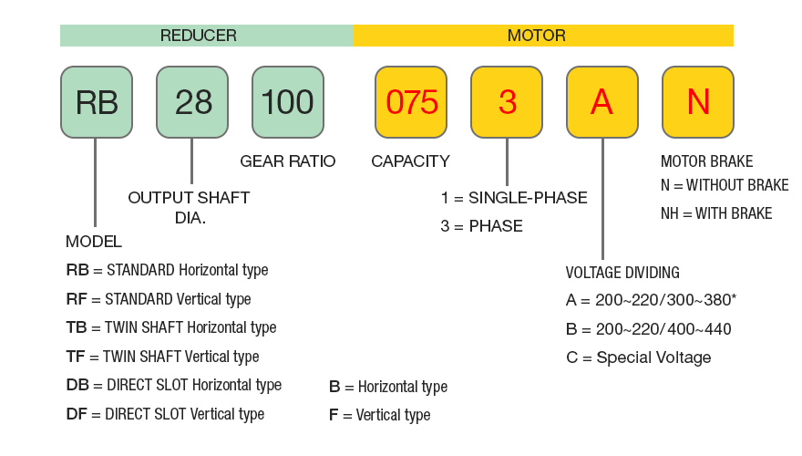
Uses The Reducer Motor
The manufacturing of the standard gear used motors are as follows : (Continuous Rated 4 Pole E insulating)
| Phases | Capacity | Frequency (Hz) | Voltage (V) | Current (A) | Rotation (R.P.M) | Cooling Method | Started by |
|---|---|---|---|---|---|---|---|
| 3 Phases | 0.1KW | 50/60/60 | 200/200/200 | 0.63/0.57/0.58 | 1410/1700/1710 | All Enclosed | - |
| 3 Phases | 0.12KW | 50/60 | 200/200 | 0.67/0.64 | 1350/1550 | All Enclosed Ext.Fan | - |
| 3 Phases | 0.2KW | 50/60/60 | 200/200/200 | 1.2/1.1/1.1 | 1410/1700/1720 | All Enclosed Ext.Fan | - |
| 3 Phases | 0.4KW | 50/60/60 | 200/200/200 | 2.2/1.93/1.95 | 1410/1700/1730 | All Enclosed Ext.Fan | - |
| 3 Phases | 0.75KW | 50/60/60 | 200/200/200 | 3.6/3.3/3.2 | 1440/1720/1740 | All Enclosed Ext.Fan | - |
| 3 Phases | 1.5KW | 50/60/60 | 200/200/200 | 6.9/6.2/6.1 | 1430/1720/1730 | All Enclosed Ext.Fan | - |
| 3 Phases | 2.2KW | 50/60/60 | 200/200/200 | 9.0/8.5/7.9 | 1430/1720/1730 | All Enclosed Ext.Fan | - |
| 1 Phases | 100KW | 50/60 | 100/110 | 3.7/3.0 | 1440/1730 | Opened drip free | Capacitor |
| 1 Phases | 200KW | 50/60 | 100/110 | 5.6/4.8 | 1440/1730 | Opened drip free | Capacitor |
| 1 Phases | 200KW | 50/60 | 100/110 | 5.7/4.9 | 1440/1730 | Opened drip free | Capacitor |
| 1 Phases | 400KW | 50/60 | 100/110 | 9.0/8.4 | 1430/1720 | Opened drip free | Capacitor |
Non-Standard Motor Assembly
Standard model of the reducer motor are of motor axle direct processing to make small size. So, the non-standard motor is hard to manufacture if the quantity is small
1 When it comes to special voltage and special treatment (heat treatment etc.) manufacturing, it must be modified from a standard motor.
2 Special motor ( outdoor, safety and explosive - proof etc. type motors) must use D type reducer.
Model selecting
1 Please select according to the applied conditions of the assembly direction.
2 It must have the output axle revolution numbers when making a selection.
3 The machine must be able to load the torque.
4 Please select based on the revolution numbers and the loading compensation torque.
5 Check the GD², Over Head Load.
| Loading Conditions | Under 3Hr daily revolution | 3~10Hr daily revolution | Over 10Hr daily revolution |
|---|---|---|---|
| General Loading | 1 | 1 | 1 |
| Light Loading | 1 | 1 | 1.25 |
| Heavy Loading | 1 | 1.25 | 1.50 |
Inertia (GD²)
When the loading GD² is large, and continuous revolution, at Starting (or with brake to stop) will produce sudden large torque which may create unexpected abnormal accident. So, the relevant machinery degree of GD² shall base on the driving connection method and starting frequency to select according to and within the numerical value range of the following table.
Allowance capacity GD² (axle or input axle conversion value)
| 3 Phase | Single Phase | Allowance GD²(kg·m²) |
|---|---|---|
| 0.1KW | 100W | 0.0029 |
| 0.12KW | 0.0030 | |
| 0.2KW | 200W | 0.0032 |
| 0.4KW | 400W | 0.0059 |
| 0.75KW | 0.0109 | |
| 1.5KW | 0.0301 | |
| 2.2KW | 0.0412 |
Allowance GD² of the compensation coefficient among the revolution conditions
| Revloution method | Frequency | Compensation Coefficient |
|---|---|---|
| No Vibration Revloution | 70 / daily | 1 |
| 70 / over 1 day | 1.5 | |
| With chain Gear connection | 70 / daily | 2 |
| 70 / over 1 day | 3 |
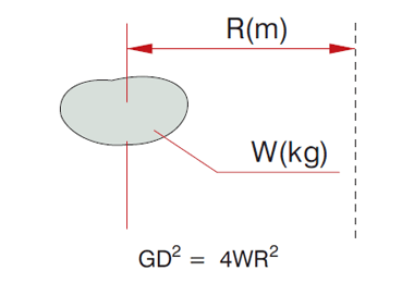
Calculation of the GD² (Gear efficiency)
The GD² generally use GD² torque 1(kg.m,sec²) to indicate. For industrial purpose, actually it is more convenient to use GD² (kg·m²)
GD² = 4 gl
G stands for weight (kg)
D stands for diameter (m)
g stands for accelerating (9.8m/sec²)
l stands for inertia torque (kg.m.sec²)
NOTE
1 If reducer input revolution is over 1800RPM. to multiple according to above numerical value (1800/input RPM²) to get the GD²
for example : 7600RPM input power is 1/4.
2 The motor axle (input axle) conversion GD² = Output axle GD² × reducing ratio.
for example : When-reducing ratio is 1/20, the GD² is 1/400.
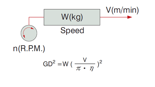
GD² at Straight Line Operation
General Conditions (kg·m²)
Horizontal Direction (Object driven) (kg·m²)
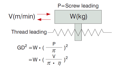
Horizontal Direction (transferring machine) (kg·m²)
Vertical Direction Crane etc. (kg·m²)
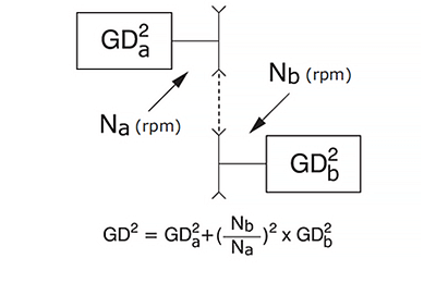
When the loaded GD² converted to N2 axle, it is.
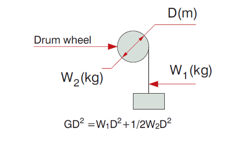
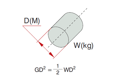
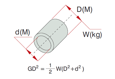
The GD² of the Revolution
Revolution center & gravity is aligned (kg·m²)
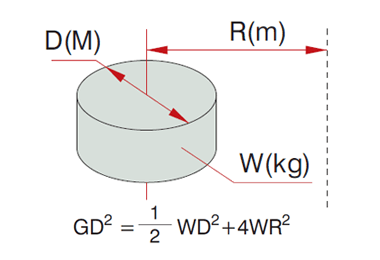
Revolution center & gravity is not aligned (kg·m²)
Suspending Load
Functioned on Over Head Load when reducer axle and the machine are connected. When applied on Chain wheel, Belt and Gear etc. must take the Over Head Load problems into consideration.
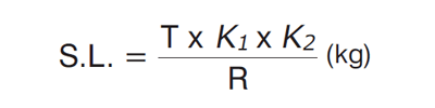
T = torque of the reducer axle (kg·m)
R = the radius of the pitch circle of chain wheel & pulley etc. of the reducer axle (m).
K1 = The coefficient of the connection method (Re : Table 5)
K2 = The coefficient of the loading position (Re : Table 6)
Compare the above stated S.L. with the allowance S.L. on Table of features.
Coefficient K1 (Table 5)
| Connection Method | K1 |
| Chains | 1.00 |
| Gears | 1.25 |
| V Shape Belt | 1.50 |
| Flat Belt | 2.50 |
Coefficient K2 (Table 6)
| Loading Position | K2 |
| Root of shaft | 0.75 |
| Center of shaft | 1.00 |
| End of shaft | 1.50 |
Loading Position
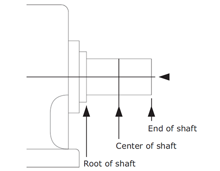
- A = Root of shaft
- B = Center of shaft
- C = End of shaft